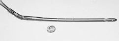
Femoral shaft fractures account for 21, 000 hospitalizations yearly and for 1. 6%of all bony injuries in children less than 18 years of age. While most pediatric femoral shaft fractures heal without significant complications, optimal treatment for children greater than six years of age remains controversial. Treatment options include traction followed by spica cast immobilization, external fixation, flexible intramedullary (IM) rods, interlocking IM nails and compression plate fixation. Each of these methods has been associated with complications. The ideal method of fracture fixation in children should sufficiently stabilize the fracture to allow rapid mobilization and joint motion while avoiding injury to the growth plate. While interlocking IM nails have been quite successful in adults, they have been associated with trochanteric growth arrest and osteonecrosis of the femoral head in children. Intramedullary fixation with flexible rods is rapidly gaining acceptance for the treatment of pediatric femur fractures since it avoids these risks. However these flexible rods provide little rotational stability and cannot be used in unstable fracture patterns (i. e. large butterfly fragment of greater than 50%of the width of the bone or with segmental comminution) . We have adapted a segmented, interlocking, titanium nail developed for treating humeral diaphysis fractures in adults (Synthes, Paoli, PA) to be used treating femoral diaphysis fractures in children six years or older (Fig. 1) . The aim of this ex-vivo, biomechanical study was to compare the structural compliance, failure load and ability of this segmented, interlocking nail to limit fracture gap motion to current methods of fixing femoral diaphysis fractures in children
 |
|
| Fig. 1 AO segmented flexible intramedullary interlocking titanium humeral nail. |
METHODS
Proportionately-sized synthetic femurs (Pacific Research, Vashon, WA)
that model the structural properties of human femurs were obtained in
29, 38 and 42 centimeter lengths representative of femurs from six, ten
and 13 year old children respectively. The size and shape of the six-year-old
synthetic femur was derived from a plaster cast of a cadaver femur obtained
from the Smithsonian Institute. We validated that the size, shape and
bending rigidities of the 38-cm. and 42-cm length synthetic femurs replicated
those of 10 and 13 year old children, respectively using three-dimensional
computed tomography scans of femurs from patients previously scanned at
Children's Hospital as part of unrelated study.
 |
|
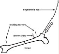
| Fig. 2 The segmented, IM humeral nail was inserted in the flexible state antegrade through an elliptically shaped lateral portal created at the greater trochanter. Proximal and distal locking screws were placed under fluoroscopic guidance. A drive screw was then advanced to tension an internal wire thereby compressing and interlocking the segments to create a rigid construct. |
An oblique, mid-shaft fracture was simulated by a 45 o osteotomy in nine femurs of each length using a handsaw and miter. Three femurs of each size were allocated to each of three fixation groups:(1) segmented, interlocking 7. 5 mm diameter titanium IM nail (Synthes, Paoli, PA) inserted laterally through the greater trochanter apophysis (Fig. 2) ;(2) two narrow diameter (3. 5 Ð4. 5 mm) , flexible stainless steel Enders IM rods (Smith Nephew, NJ) inserted retrograde through the medial and lateral distal metaphysis;(3) four pin (4. 5mm Shanz screw) , double stacked, carbon-fiber rod, AO external fixator mounted laterally (Synthes, Paoli, PA) . Since connective tissues were absent, fracture stability was provided solely by the hardware. The distal end of each femur was potted in methylmethacrylate and the proximal end was potted in a low melting point metal that allowed non-destructive removal of the femoral head from the potting material. Fracture gap motion was measured using two video cameras and a set of four infrared reflective markers attached to both sides of the osteotomy to monitor the rigid body motion of each fragment. The maximum fracture gap displacement was determined from the difference in rigid body motion of the two femur segments in three dimensions. Specially designed loading frames mounted in a servohydraulic testing machine (Instron 1331, Canton MA) operated under load control allowed the application of four-point bending moments in the frontal and sagittal planes (Fig. 3) , torsional moments along the femoral diaphyseal axis (Fig. 4) and a multiaxial, multimodal loading configuration that simulated single legged stance (Fig. 5) . Allowing the femurs to warp or slide out of plane eliminated the application of extraneous forces and moments. Structural compliance was derived from the slope of the displacement-load curve for each mode of testing. This parameter is the inverse of stuffiness and quantifies the overall motion or displacement of the stabilized femur construct in response to an applied load. The specimens were then loaded to failure in single legged stance. Failure was defined as the load at which the displacement-load curve deviated 2%from the linear portion of the curve. Compliance, maximum fracture gap displacement and failure load were compared for each type of fixation and for each femur size for every loading mode. Two-way analysis of variance was performed to examine the effect of fixation type and femur size on compliance, fracture gap displacement and failure load.
 |
 |
|
|
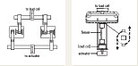
Fig. 3 (left) A specially designed loading frame mounted in a servohydraulic materials testing machine allowed the application of four-point bending in either the frontal or sagittal planes. A non-destructive physiologic moment of 6. 35 Nm was applied for five cycles at 0. 5 Hz. Fig. 4 (right) A force couple applied using a cable drive system mounted in a servohydraulic material testing system imposed a torque of 4. 14 Nm for five cycles at 0. 5 Hz along the femoral diaphysis. This cable drive system allowed the femur to warp out of plane while maintaining a relatively constant torque about the femoral diaphysis and eliminated the imposition of extraneous forces and moments. A sixdegree-of-freedom load cell was used to monitor these parasitic forces and moments. |
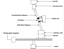
Fig. 5 Single-legged stance loading was simulated by applying a uniaxial compressive load to the femoral head at a specific solid angle relative to the femoral diaphysis. A sliding plate eliminated the creation of progressive bending moments at the level of the distal femur. The femur was mounted in a servohydraulic material testing system between a pair of six-degree-of-freedom load cells to measure applied loads at the hip and reaction forces and moments at the distal femur. A 200N load was applied to the hip for five cycles at 0. 5Hz to measure fracture gap displacement in single-legged stance. A progressive load was then applied to the hip at 10mm/sec ramp to a stroke displacement of 90mm to fail the femoral construct. |
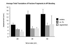 |
| Fig. 6 Fracture Gap displacement for flexion /extension bending in sagittal plane |
RESULTS
COMPLIANCE
Both femur size and fixation type affected structural compliance in bending,
torsion and single legged stance. The effect of fixation type was influenced
by femur size. Intramedullary devices were more compliant in the larger
femurs. We found that the external fixator was the least compliant for
all testing modes and all femur sizes. The segmented IM nail was less
compliant than the Enders rods in torsion and in single legged stance,
but in bending the segmented nail was different from the Enders rod only
for the smallest femur.
FRACTURE
GAP DISPLACEMENT
Both femur size and fixation type affected fracture gap displacement for
flexion /extension bending in the sagittal plane (Fig.
6) . There was more gap motion in larger femurs. There was also
more gap motion for Enders rods than for the segmented nail or external
fixator. The fracture gap displacement in flexion/extension bending was
not significantly different between the segmented nail and external fixator.
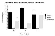
Only the type of fixation used affected fracture gap displacement for
varus/valgus bending in the frontal plane (Fig.
7) . There was more gap displacement for Enders rods than for the
segmented nail or external fixator.
The external fixator ad the least gap motion since the hardware lies in the frontal plane and is therefore best at resisting bending loads applied in this plane. Fracture gap motion in varus/valgus bending was significantly less for the segmented nail compared to the Enders rods.
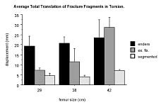
Both femur size and the type of fixation used affected fracture gap displacement for torsion along the femoral shaft (Fig 8) . Femur size influenced the effect of fixation type. There was more fracture gap displacement in the larger femurs. Fracture gap displacement was the least for the segmented nail for all sized femurs compared to Enders and the external fixator. Fracture gap displacement in torsion was greatest for the Enders rods, except for the largest femur, since the rods are not interlocked or rigidly attached to either fracture segment.
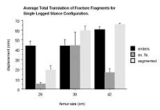
Both femur size and fixation type affected fracture gap displacement in single-legged stance (Fig. 9) . The effect of fixation type was influenced by femur size. There was more fracture gap displacement in the larger femurs. Fracture gap displacement was the smallest for the external fixator for all sized femurs.
 |
 |
|
|
Fig. 7 Fracture Gap displacement for varus /valgus bending in frontal plane |
Fig. 9 Fracture Gap displacement for single-legged stance | |
 |
 |
|
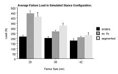
| Fig. 8 Fracture Gap displacement for axial torsion | Fig. 10 Failure Load for single-legged stance |
FAILURE
LOAD
Both femur size and the type of fixation used affected the failure load
in single legged stance (Fig. 10) .
Femur size influenced the effect of fixation type on failure load. Failure
loads were greater for smaller femurs since the hardware was proportionately
more rigid. (Structural rigidity depends on the radius of the femoral
diaphysis raised to the fourth power; therefore smaller femurs are less
rigid relative to the rigidity of the hardware which was similar for all
sized femurs. ) Enders rods were weakest. The failure loads were not significantly
different between the external fixator and the segmented nail.
DISCUSSION
Stable fixation implies little fracture displacement under load. The relative
motion of fracture fragments under load determines the morphologic features
of fracture repair. The interfragmentary strain hypothesis proposed by
Perren suggests that the relative displacement of fracture fragments under
load versus the initial fracture gap width govern the type of tissue that
forms between fracture fragments. Bone formation requires interfragmentary
strains of less than 2%. While the original interfragmentary strain theory
considered only longitudinal strains and is not entirely consistent with
analytical three-dimensional analyses or in-vivo experimental studies,
this theory does provide a model for predicting healing response. We assume
that the method of fracture fixation that limits interfragmentary strain
most and has the highest failure load is the most likely to facilitate
fracture healing. While it is recognized that this assumption ignores
the important biologic components of fracture healing that can only be
assessed invivo, it does allows us to compare the performance of the segmented
interlocking humeral nail to existing methods of femoral diaphysis fixation
currently used for treating pediatric femur fractures. Since fracture
stability was provided only by the hardware, without additional support
from the surrounding soft tissues, this analysis can be assumed to provide
a worst case scenario.
The segmented, interlocked, intramedullary nail stabilized simulated femoral shaft fratures better than Enders IM nails and the external fixator in proportionately sized synthetic femurs subjected to bending and axial torsion. The external fixator was best at minimizing fracture gap displacement for varus /valgus bending in the frontal plane and single-legged stance since the proximity of the inner pins to the fracture gap decreased the unsupported (or working) length better than the segmented 7. 5 mm intramedullary nail which was interlocked at the proximal and distal ends of the femur. Failure loads were higher for the segmented nail compared to Enders and equivalent to the external fixator. Since the rigidity of the intramedullary nail varies as the fourth power of the nail radius, a larger diameter nail (when available) will be more rigid and will be better able to stabilize fractures in larger femurs. Besides the improved rigidity of larger diameter nails, the better interference fit within the medullary canal will decrease the unsupported length of the fracture segments and further decrease fracture gap displacement.
ACKNOWLEGMENT
This study funded by AO/ASIF Foundation grant. Synthes North America and
Smith Nephew provided materials. Fluoroscopic imaging was provided by
OEC.
W Bartholomew, BS , Research Staff, Orthopaedics Biomechanics Laboratories, Beth Israel Deaconess Medical Center, Boston, MA.
S Kwak, PhD , Research Staff, Orthopaedics Biomechanics Laboratories, Beth Israel Deaconess Medical Center, Boston, MA.
D Ring, MD is an Instructor in Orthopaedic Surgery at Harvard Medical School.
B Snyder, MD, PhD is an Assistant Professor in Orthopaedic Surgery at Harvard Medical School.
Address correspondence to:
Brian D. Snyder, MD, PhD
Department of Orthopaedic Surgery
The Children's Hospital
300 Longwood Avenue
Boston, MA 02115