
Original Submissions
Current Issue: Volume 14 |  PDF
PDF
Hindfoot Alignment in Surgical Planning for Total Knee Arthroplasty
1Center for Advanced Orthopaedic Studies, Department of Orthopaedic Surgery, Beth Israel Deaconess Medical Center, Harvard Medical School, Boston, MA
2Department of Orthopaedic Surgery, Beth Israel Deaconess Medical Center, Harvard Medical School, Boston, MA
PDF
Background
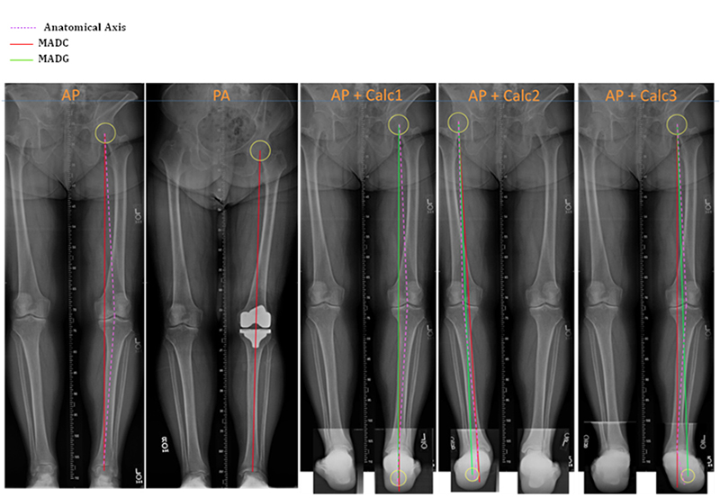
Numerous biomechanical factors, including malalignment of the lower limbs, are associated with increased force across the joints leading to higher incidence and progression of OA of the knee and ankle.1 Traditionally, this mechanical axis deviation has been measured from the center of the femoral head to the center of the ankle and is called the conventional mechanical axis deviation (MADC). However, numerous studies have indicated that a more accurate measurement of the actual weightbearing axis would also account for hindfoot malalignment distal to the ankle, including the subtalar joint.2-6 This axis can be measured from the center of the femoral head to the ground reaction point and is called the ground mechanical axis deviation (MADG).
The relationship between knee OA and hindfoot deformity has been examined in the literature. Though no predictable relationship between knee and hindfoot malalignment has been found, it is known that a significant number of patients with knee OA will also have some degree of hindfoot deformity.6-7 The importance of precise alignment for knee implant success cannot be underestimated, as even a minor deviation can lead to increased edge loading, polyethylene implant wear, early failure and subluxation.8 As such, a more accurate measurement for operative planning that accounts for alignment distal to the ankle, such as MADG, is desirable. We designed a dynamic computer model to compare measures of malalignment using MADC and MADG. We hypothesized that there would be a significant difference between estimates using MADC and those where MADG was used. We will now bring our focus to the biomechanics laboratory where we aim to compare load transmission applied at the femoral head using MADC and MADG on a cadaveric model. We hypothesized that MADG would prove a superior method for predicting actual weightbearing axis of the lower extremity.
Methods
Sample lower extremity x-rays combining standard AP radiographs with hindfoot alignment views were compared for estimated MADC and MADG. (Figure 1) Computer simulation free-body diagrams of single leg stance, double leg stance, toe off and heel strike were drawn and geometrically compared using MADC and MADG. Length of tibia (286.5 mm), femur (353.5 mm) and the height of foot (70.6 mm) were derived from anthropological data of an average adult male.9 Guichet et al.’s predicted trigonometry equation was coded in MATLAB and used to derive MADC and MADG for each stance over a range of foot-tibial angles and genu valgum angles at the knee.3 By convention, valgus deviations were considered positive and varus deviations were considered negative. A 3D graph was plotted to illustrate the differences between MADC and MADG for a given angle of deformity in each stance.
In the laboratory, baseline measurements of anatomic axis, MADC and MADG will be recorded for 14 cadaveric lower extremity specimens. We have designed and are building a biomechanical testing jig to apply load to the specimens. The jig will be constructed using a hydraulic jack to apply load to the femoral head at an angle calculated to simulate physiologic loading. We will measure the load transmitted through the medial and lateral knee joint, the center of the ankle joint and the ground reaction point of the calcaneus. Loads measured at the center of the ankle and the ground reaction point will be compared to determine which more accurately estimate actual load transmission. Deformities at the level of the hindfoot will then be created by an orthopaedic surgeon to simulate typical physiologic malalignments. Load transmissions at the knee, ankle and hinfoot will be measured to determine the weightbearing axis in the setting of hindfoot deformity.
 All Rights Reserved. Permission For Use Required.
Results
Using the computer model, the two evaluative methods, MADC and MADG, produced greatly varying results. MADG significantly exceeded MADC values, which stresses the severity of the malalignment. Higher angles of hindfoot deformity were associated with greater MADG from anatomical axis. In future studies using the cadaveric model, we expect to find that load measured at the ground reaction point is closer to the actual force applied when compared with load measured at the center of the ankle. This difference between measured load transmission at the center of the ankle and the ground reaction point should be greater for each specimen after hindfoot deformity has been simulated. Based on our computer model findings, we also expect that knees implanted using MADC to plan realignment will demonstrate more uneven loading at the medial and lateral knee joint when compared to those implanted using MADG for surgical planning.
Conclusions
The results of this analysis so far illustrate that the incorporation of hindfoot deformity into calculation of mechanical axis deviation creates a more dynamic model. MADG results for each stance appeared much wider than MADC, which suggests possible errors due to the limited number of parameters used for MADC. Where MADC accounts for only length of tibia, length of femur and genu-valgum angle, MADG also considers height of foot, valgus angle of foot and theta (angle between the line joining the sole of the foot to the knee and the femur) in addition to these conventional parameters.
In conclusion, it is essential to accurately evaluate limb mechanics. Planning for knee and ankle surgery and arthroplasty requires the evaluation of the conventional mechanical axis alignment as well as hindfoot malalignment. Precise and comprehensive evaluation will reduce the risks of postoperative malalignment, early failure of osteotomies and increased wear of polyethylene components in knee arthroplasty. Future work will include application of our findings to a cadaveric model.
References