| HOJ HOME | Chiefs Reports | Osgood Day | Scientific Articles | Alumni Association |
|
| Click here to visit our web site |
| |||||||||||||||||||||||||||||||||||
|
Since the introduction
of total hip arthroplasty (THA), generation of wear debris has been a
major concern of orthopaedic surgeons. Although initial concerns were
focused on the longevity of the implant, we now know that osteolysis associated
with wear debris is the primary long-term problem in total hip replacement.
Charnley noted early, rapid, unacceptable wear with Teflon (1) . With
the advent of ultra-high molecular weight polyethylene (UHMWPE), considerable
reduction in wear was achieved, but wear has remained as a dominant long-term
problem. Thus, the accuracy and reliability of the clinical assessment
of wear remains a controversial topic. Techniques for measuring wear,
including uniradiographic, duo-radiographic, edge detection, and radiostereometry,
have all been reported (2,4,6,11-18) . The additions of wire markers to
poly-ethylene cups, radio-opaque cement, and metal-backed shells have
altered the techniques of wear assessment. It is now generally accepted
that polyethylene wear debris is the major cause of osteolysis following
total hip arthroplasty (3) . Measuring wear in the laboratory on retrieved
specimens can be done with great accuracy. Measuring wear in vivo, however,
is more challenging. The purpose of this article is to review radiographic
techniques for assessing in vivo polyethylene wear in total hip arthroplasty.
The first study to evaluate wear following THA was conducted by Charnley and Cupic (2) . Although the primary aim of this study was to evaluate the ten-year results for their low friction arthroplasty, it was the first in vivo measurement of poly-ethylene wear. Wear was assessed by a uni-radiographic technique using only the most recent radiograph. The narrowest measurement in the weightbearing area was subtracted from the widest measurement in the non-weight bearing area and divided by two, resulting in total wear. Total wear was then divided by the number of years and expressed as millimeters (mm)/year. The accuracy of this method was estimated by Charnley to be within 0.5 mm. Average wear in this series was reported as 0.12mm/year. No correlation was found with activity level, sex, age or weight. This measurement technique was felt to be attractive because it could be performed with a single radiograph and there was no need for correction of magnifica-tion. Criticisms of the technique were that the wear was measured entirely within the direction of the plane of the opening of the socket, when in fact the maximum wear actually occurred in the weight bearing area. In 1975, Charnley and Halley addressed wear in the same 72 patients using a duo-radiographic technique (4) . Thickness of the polyethylene was measured from the most recent radiograph and subtracted from a similar measurement taken from the earliest radiograph at the same point. Both measurements were corrected for magnification using the head diameter of 22.25mm. The results of wear measurements over ten years were slightly higher than those reported utilizing the previous uni-radiographic technique (mean 0.15mm/year, range 0 0.45 mm/year). It was noted that the direction of wear was upward and outward in 64% of the patients, vertical in 32%, and medial only in 3%. The authors postulated that the underestimate of wear using the uni-radiographic technique was secondary to the vertical nature of the wear pattern. The reported accuracy of this duo-radiographic technique was comparable to the uni-radiographic technique to within 0.5mm. In 1976, Clarke et al. challenged the concept of in vivo wear measurement using standardized radiographs (5) . They concluded that it was impossible to accurately measure wear using uni-radiographic or duo radiographic techniques due to the number of variables. They noted that the accuracy of measuring a known entity (e.g., a 22.25 mm femoral head) from a radiograph was 0.5mm. They determined that the duo-radioagraphic technique was superior to the uni-radiographic technique in some circumstances. However, they found error measurements of the same order as wear magnitudes using both techniques. This was particularly true with increased anteversion of the socket, which altered the position of the wire embedded in the polyethylene out of the coronal plane. They concluded that it was not possible to accurately measure wear from clinical radiographs. In 1979, Griffith et al. questioned the experimental design, the use of anteversion of the socket, and lack of use of radioopaque bone cement in the study of Clarke et al. They evaluated a different set of patients with an average of 8.3-year fol-low- up and found an average wear rate of 0.07mm/year. The issue of variable anteversion was addressed by aligning the wire in the coronal plane on the radiograph in an experimental model. Anteversion greater than 10 degrees did significantly change the accuracy of the wear measurements. The question of the accuracy of centering of the x-ray beam over the symphysis pubis was also addressed. It was found that a change of 4.5 inches from the symphysis pubis altered the measurements by only 0.2mm. Others, including Beckenbaugh and Ilstrup (7) and Rose and Radin (8) , also challenged the accuracy of radiographic evaluation of wear. In the 1980's, more retrieval studies were conducted to compare radiographic wear estimation to true wear. Wroblewski analyzed 22 retrieval specimens with acrylic casts to determine wear and compared these results with those obtained from radiographic wear measurements (9) . He found a mean rate of real wear of 0.19mm/year and a radiographic rate of wear of 0.21mm/year using the duo-radiographic technique. Rimnac et al. reported similar results in their analysis of 10 retrieved polyethylene cups with significant wear (10) . In 1990, Livermore published on a duo-radiograph technique that has become the most commonly used technique among researchers reporting wear measurements (11) . To eliminate concern regarding anteversion, the cementprosthesis interface is used to identify the polyethylene border. This technique uses concentric circles to locate the center of the femoral head. Magnification is corrected according to the following equation: correction factor = known diameter divided by apparent radiographic diameter On the most recent radiograph, the shortest distance from the center of the femoral head to the edge of the cup-cement interface is identified. The thickness of the polyethylene in line with this measurement is noted. Returning to the earliest radi-ograph, the polyethylene thickness is measured in the same line, again correcting for magnification. The difference between the two measurements is an estimate of the polyethylene wear. Volumetric wear is calculated using the following equation: v = ð r 2 w where v = amount of volumetric wear, r = femoral head radius, and w = linear migration. The reliability of this method was tested against a small series of twelve retrievals. The authors reported a mean discrepancy of only 0.075 mm (range 0 to 0.4mm) between direct and radiographic measure-ments of polyethylene thickness.
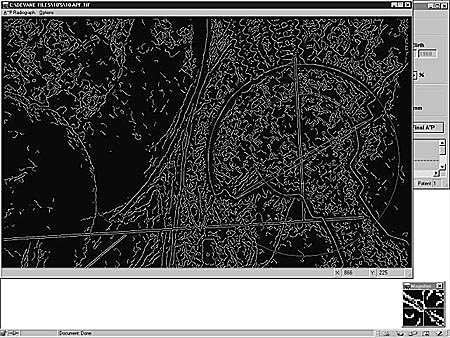
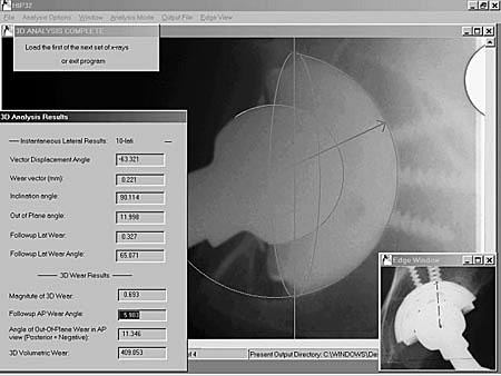
The commonly used
Devane technique is a computer-aided design (CAD) approach to dual (anteroposterior
and lateral) radiograph analysis (Figure 1) (14) . The first step of the
analysis procedure is passing the image through low pass and high pass
filters to minimize image noise. An edge detection sequence filter is
then used to identify edge pixel sequences. Operator identification of
candidate edges for the head and the cup are then used for identifying
the best fitting circles based on a least-squares fit regression approach.
This analysis uses a CAD model of the hardware already defined in the
program and specified by the user (e.g. Harris-Galante I acetabular cup).
The x-ray beam is positioned with the beam center at a user specified
point and x-ray source 101.6 cm above the beam center. It then projects
a beam from that source through the cup. By analyzing the magnification
on the radiograph, the actual distance that the cup had originally been
positioned above the film can be determined, and a modal plain in which
the true AP movements took place can be modeled in three- dimensional
space. The lateral images are used to specify the location in the vertical
orientation of the cup and head in three-dimensional space. In this way,
the Devane technique creates a three-dimensional model of the position
of the hardware.
The most precise in vivo method of quantifying wear measurements is radiostereometry (RSA). The accuracy of distance measurements using RSA has been confirmed to be within 0.01mm (17) . This technique involves implanting a series of multiple tantalum markers into bony landmarks near the acetabular and femoral implants. Digital radiographs are taken within a reference cage from two independent directions at given distances and angles. The center of the femoral head is determined and coordinated in three dimensions. The cup markers are also determined in three dimensions. The migration of the femoral head in reference to the fixed position of the cup markers represents polyethylene wear (18) . Despite its accuracy, RSA is a complex procedure both to carry out and to analyze over time. As a result, most research series that have been reported using this technique have had small numbers of patients and surgeons enrolled. The use of this technique is currently being evaluated in our laboratory. In order to complete multi-center evaluations of polyethylene wear, the ideal in vivo method is one that relies on a reproducible radiographic technique. A comparison of the data input, analysis methodology, and potential strengths and limitations of the previously mentioned contemporary techniques is presented in Table I. Advances in the current plain radiograph based techniques are likely to originate from: 1) refined optical scanner hardware performance, 2) integration of strengths of each methodology, 3) a better understanding of the multi-directional nature of the wear, 4) potential computation of wear from a single, more informative radiograph, and 5) illumination of the importance of supine versus prone radiography. Ultimately, the accuracy of these techniques will be limited by the size of the digital x-ray pixel in the discrete space of the radiographic representation. With the recent introduction
of new highly cross-linked polyethylenes, assessment of in vivo wear of
these materials is even more critical than ever. Because wear associated
osteolysis is usually not present until five to ten years following primary
THA, improved techniques are needed to assess polyethylene wear. Our laboratory
continues to evaluate analysis tech-niques for accuracy, precision, and
reproducibility with the goal of detecting in vivo wear earlier and more
reliably.
|
|||||||||||||||||||||||||||||||||||
|
|||||||||||||||||||||||||||||||||||
| HOJ HOME | Chiefs Reports | Osgood Day | Scientific Articles | Alumni Association |
| References | |
| 1. | Charnley, J Low Friction Arthroplasty. Springer Verlag, Berlin, 1979, p 7. |
| 2. | Charnley, J.; and Cupic, Z.: The nine and ten year results of the low-friction arthroplasty of the hip. Clin. Orthop., 95: 9-25, 1975. |
| 3. | Harris, W. H.: The problem is osteolysis. Clin. Orthop., 311: 46-53, 1995 |
| 4. | Charnley, J.; and Halley, J. K.: Rate of wear in total hip replacement. Clin. Orthop., 112: 170-179, 1975. |
| 5. | Clarke, J. C.; Black, K.; Rennie, C.; and Amstutz, H. C.: Can wear in total hip arthroplasties can be assessed from radiographs? Clin. Orthop., 121: 126-142, 1976. |
| 6. | Griffith, M. J.; Seidenstein, M. K.; Williams, D.; and Charnley, J.: Socket wear in Charnley low friction arthroplasty of the hip. Clin. Orthop., 137: 37-47, 1978. |
| 7. | Beckenbaugh, R. D., and Ilstrup, D.M.: Total hip arthroplasty. J. Bone Joint Surg., 60-A: 306-313, 1978 |
| 8. | Rose, R. M.; and Radin, E. L.: Wear of polyethylene in the total hip prosthesis. Clin. Orthop., 170: 107-115, 1982. |
| 9. | Wroblewski, B. M:M: Direction and rate of wear in Charnley low-friction arthroplasty. J. Bone and Joint Surg., 67-B: 757-761, 1985. |
| 10. | Rimnac, C. M.; Wilson, P. D. J.; Fuchs, M. D.; and Wright, T. M.: Acetabular cup wear in total hip arthroplasty. Orthop. Clin. North Am., 19: 631-636, 1988. |
| 11. | Livermore, J.; Ilstrup, D.; and Morrey, B.: Effect of femoral head size on wear of the polyethylene acetabular component. J. Bone and Joint Surg., 72-A: 518-528, 1990. |
| 12. | Krismer, M., Bauer, R., Tschupik, J., and Mayrhofer, P.: ERBA: a method top measure migration of acetabular components. J. Biomech, 28: 1225-1236, 1995. |
| 13. | Shaver, S. M.; Brown, T. D.; Hillis, S. L.; and Callaghan, J. J.: Digital edge-detection measurement of polyethylene wear after total hip arthroplasty. J. Bone and Joint Surg., 79-A: 690-700, 1997. |
| 14. | Devane, P. A.; Bourne, R. B.; Rorabeck, C. H.; Hardie, R. M.; and Horne, J. G.: Measurement of polyethylene wear in metal-backed acetabular cups. I. Three-dimen-sional technique. Clin. Orthop., 319: 303-316, 1995. |
| 15. | Devane, P. A.; Bourne, R. B.; Rorabeck, C. H.; MacDonald, S.; and Robinson, E. J.: Measurement of polyethylene wear in metal-backed acetabular cups. II. Clinical application. Clin. Orthop., 319: 317-326, 1995. |
| 16. | Martell, J. M.; and Berdia, S. Determination of wear in total hip replacements with use of digital radiographs. J. Bone and Joint Surg., 79-A: 1635-1641, 1997. |
| 17. | Selvik, G., Alberius, P., and Aronson, A. S.:A roenstereophotogrammetric system. Construction, calibration and technical accuracy. Acta Radiol Diagn Stockh, 24:343- 352, 1983. |
| 18. | Karrholm, J., Herbets, P., Hultmark, P., Malchau, H., Nivbrant, B., and Thanner, J.: Radiostereometry of hip prostheses. Review of methodology and clinical results. Clin. Orthop, 344: 94-110, 1997. |
|
TOP OF PAGE | HOJ HOME |
| HOJ HOME | Chiefs Reports | Osgood Day | Scientific Articles | Alumni Association |